A drone battery pack should be sized by working backward from the UAV’s actual mission and electrical requirements. Start with pack voltage and current demand, calculate how much usable energy the mission requires, convert that energy into preliminary capacity, and then check whether the resulting battery still fits the aircraft’s weight and space limits.
The process is iterative. A larger battery changes aircraft mass, and that added mass can change the power required to fly. The first calculation therefore provides a starting battery specification, not a guaranteed final pack or guaranteed flight time.
A practical sizing sequence is:
Mission Requirements → Voltage → Current → Energy → Capacity → Weight → Space → Recalculate → Validate
Define the UAV Requirements Before Calculating the Battery
Battery sizing is only as reliable as the inputs used to calculate it. Before choosing cells or deciding how many amp-hours the pack should contain, define how the UAV is expected to operate.
Useful starting inputs include:
- Target mission duration
- Aircraft type
- Payload
- Propulsion-system voltage
- Average mission power or current
- Peak current during takeoff, climb, or acceleration
- Maximum battery weight
- Available battery-bay dimensions
- Connector and interface requirements
Average power is especially important. Using the maximum motor rating for the entire mission can greatly overestimate energy demand, while using only a light-cruise figure can underestimate it.
Where possible, average mission demand should come from flight logs, bench measurements, propulsion data, or representative hover and cruise current measurements.
Professional custom-UAV battery projects normally collect these aircraft-level inputs before pack design begins. Custom UAV battery development commonly starts with voltage, capacity, continuous current, peak current, space, weight, connector, and interface requirements.
Good battery sizing begins with a realistic load profile, not with a target mAh number.
Step 1: Set Pack Voltage and Current Capability
Voltage defines the electrical platform of the battery pack. Current capability determines whether that battery can safely support the propulsion load.
Choose the Pack Voltage
For lithium battery packs, cells connected in series increase the total pack voltage.
A basic relationship is:
Pack Nominal Voltage = Cell Nominal Voltage × Number of Cells in Series
For example, if a lithium-ion cell has a nominal voltage of 3.7 V, a 12-series configuration gives:
12 × 3.7 V = 44.4 V nominal
But nominal voltage is not the only number that matters.
If the selected cell reaches 4.2 V when fully charged, the same 12S pack can reach:
12 × 4.2 V = 50.4 V fully charged
Motors, ESCs, onboard electronics, wiring, protection devices, and chargers therefore need to be compatible with the complete battery operating-voltage range.
Higher voltage can reduce current for the same electrical power. The basic relationship is:
Current ≈ Power ÷ Voltage
Suppose a propulsion system requires approximately 2,000 W during a particular operating condition.
At 22.2 V:
2,000 ÷ 22.2 ≈ 90 A
At 44.4 V:
2,000 ÷ 44.4 ≈ 45 A
This does not mean that 44.4 V is automatically the better UAV architecture. It simply shows why voltage selection directly affects current, wiring, connectors, ESC requirements, and pack configuration.
Determine Continuous and Peak Current
The pack must support at least two current conditions:
Continuous current is the normal electrical demand during sustained flight.
Peak current is the higher short-duration demand during takeoff, rapid climbing, acceleration, strong maneuvering, or heavy-load events.
Both should be evaluated with suitable margin.
For cylindrical lithium-ion packs, increasing the number of cells in parallel can raise both capacity and available current. For example, if one cell is rated for 15 A continuous discharge under the relevant conditions:
- 1P may provide approximately 15 A
- 2P may provide approximately 30 A
- 3P may provide approximately 45 A
This simplified relationship assumes appropriate current sharing and does not override real pack limitations.
The final current capability may also be limited by:
- Cell temperature
- Busbars and interconnects
- Wire gauge
- Connector rating
- BMS or protection hardware
- Pack cooling
ArduPilot’s battery-management functions also recognize current as a real operating constraint. Its current-limiting and voltage-scaling functions can reduce throttle when configured battery-current limits are exceeded.
A correct pack voltage is not enough; the battery must also support the actual continuous and peak load.
Step 2: Convert Mission Time into Required Energy and Capacity
Once voltage and approximate power demand are known, mission duration can be converted into a preliminary energy requirement.
A useful first-pass relationship is:
Mission Energy (Wh) ≈ Average Power (W) × Mission Time (h)
Consider a simplified example:
- Average mission power: 800 W
- Target powered mission duration: 30 minutes
Thirty minutes equals 0.5 hours, so:
800 W × 0.5 h = 400 Wh
The aircraft therefore needs approximately 400 Wh of usable mission energy under the assumed 800 W average-power condition.
However, a battery should not normally be sized with the assumption that 100% of its nominal energy will be consumed during the planned mission.
Some energy needs to remain available for reserve, landing, unexpected maneuvering, voltage limits, and normal operating margin.
If the engineering assumption allocates 80% of nominal pack energy to the planned mission:
Required Nominal Pack Energy = 400 Wh ÷ 0.80 = 500 Wh
If the selected nominal voltage is 44.4 V:
Capacity = 500 Wh ÷ 44.4 V ≈ 11.3 Ah
The first-pass specification is therefore approximately:
44.4 V / 11.3 Ah / 500 Wh
This number is useful, but it is not the end of the design process.
It also does not guarantee that the UAV will fly for 30 minutes.
The estimate assumes that average mission power remains around 800 W. Actual demand may change after the final battery weight, payload, wind, flight profile, propulsion efficiency, temperature, and maneuvering requirements are known.
Experimental UAV powertrain research similarly estimates endurance by combining battery capacity, usable discharge, and measured or expected operating current rather than treating nameplate capacity as a guaranteed flight-duration value. Measured powertrain behavior remains necessary when refining theoretical battery estimates.
Step 3: Check Whether the Calculated Battery Becomes Too Heavy
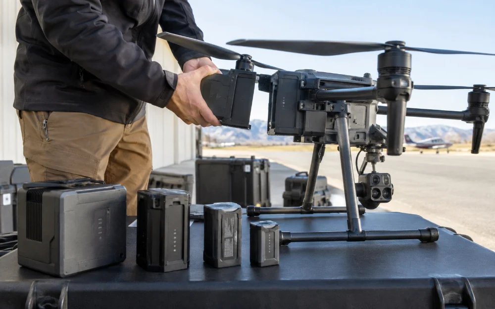
A calculated 500 Wh requirement does not tell you whether the resulting battery is practical for the aircraft.
The next question is:
How much will the complete pack weigh?
Battery mass depends on more than the cells themselves. A finished UAV battery may include:
- Cells
- Busbars or interconnects
- Wiring
- Connector
- Protection or BMS hardware
- Temperature sensing
- Insulation
- Enclosure or mechanical support
For preliminary engineering, pack weight can be estimated from the expected pack-level energy density of the proposed design:
Estimated Pack Mass ≈ Required Pack Energy ÷ Expected Pack-Level Energy Density
However, there is no single Wh/kg value that should be assumed for every UAV battery. Different cell chemistries, cylindrical or pouch formats, structural requirements, wiring, BMS hardware, and protection strategies can produce very different finished-pack values.
Use a realistic pack-level estimate based on the actual cells and architecture being considered.
Once the estimated battery mass is known, add it back into the aircraft model and recheck:
- Maximum takeoff weight
- Payload margin
- Hover or cruise power
- Continuous current
- Peak current
- Thrust-to-weight ratio
If the new battery substantially changes aircraft mass, the original 800 W average-power assumption may no longer be valid.
The sizing loop therefore becomes:
Calculate Energy → Estimate Pack Weight → Update Aircraft Mass → Recalculate Power → Adjust Battery Size
UAV propulsion-sizing research also treats battery mass, aircraft mass, power demand, and endurance as coupled variables rather than independent inputs. Battery sizing therefore benefits from iteration rather than a single capacity calculation.
Step 4: Fit the Battery into the Available Space
A battery can satisfy the electrical calculations and still be impossible to integrate into the UAV.
Physical space should therefore be treated as a sizing constraint from the beginning.
Define at least:
- Maximum pack length
- Maximum pack width
- Maximum pack height
- Maximum finished weight
- Mounting orientation
- Connector position
- Cable exit direction
- Removal and service access
- Center-of-gravity constraints
For example, an electrically suitable 12S cylindrical-cell configuration may require a series-parallel arrangement that is too wide or too long for the available battery bay.
Possible engineering responses might include:
- Changing the cell format
- Changing the parallel arrangement
- Reorienting the cell layout
- Using a split-pack architecture
- Changing battery placement within the aircraft
Each of these decisions can affect wiring, weight distribution, current path, mechanical protection, and center of gravity.
This is why physical envelope information is routinely requested for custom UAV battery projects alongside electrical requirements. Battery dimensions, weight, connector layout, and integration constraints are part of the engineering input—not final packaging details.
A mathematically correct battery specification is not useful if the pack cannot physically fit the aircraft.
Put It Together: A Practical First-Pass UAV Battery Specification
The following example combines the main sizing steps into one preliminary engineering workflow.
| Input | Example Value |
|---|---|
| Nominal Pack Voltage | 44.4 V |
| Average Mission Power | 800 W |
| Target Powered Mission Time | 30 min |
| Planned Usable Energy Fraction | 80% |
| Estimated Peak Current | 70 A |
| Maximum Battery Mass | Project-defined |
| Available Battery Bay | Project-defined |
Step 1 — Calculate Mission Energy
800 W × 0.5 h = 400 Wh
The estimated mission therefore requires approximately 400 Wh of usable energy under the assumed operating condition.
Step 2 — Add the Planned Reserve
400 Wh ÷ 0.80 = 500 Wh nominal energy
The preliminary pack should therefore contain approximately 500 Wh of nominal energy.
Step 3 — Convert Energy to Capacity
500 Wh ÷ 44.4 V ≈ 11.3 Ah
The preliminary capacity is approximately 11.3 Ah.
Step 4 — Check Current Capability
The finished battery must support the expected continuous mission current and the estimated 70 A peak load with appropriate engineering margin.
The final current rating must consider the complete path:
- Cells
- Parallel count
- Busbars
- BMS or protection system
- Wiring
- Connector
Step 5 — Check Mass and Mechanical Envelope
Estimate the finished pack weight and physical dimensions, add that mass to the aircraft model, and verify that the pack fits the battery bay without creating unacceptable center-of-gravity or payload problems.
The resulting first-pass specification might therefore look like:
Approximately 44.4 V / 11.3 Ah / 500 Wh, with continuous and peak current capability, maximum weight, and physical dimensions defined by the aircraft requirements.
This is a useful engineering starting point—not a finished production battery.
Bench testing, pack validation, and real aircraft testing are still required before the design can be treated as final.
| Sizing Parameter | What You Need | What It Determines |
|---|---|---|
| Mission Time | Target powered duration | Required energy |
| Average Power | Typical mission demand | Wh requirement |
| Voltage | Propulsion architecture | Series count |
| Continuous Current | Normal operating load | Cell and parallel sizing |
| Peak Current | Takeoff and climb demand | Discharge capability |
| Usable Energy Fraction | Planned operating reserve | Nominal pack energy |
| Maximum Weight | Aircraft weight budget | Feasible pack size |
| Available Space | Battery-bay dimensions | Mechanical architecture |
| Connector | Current and interface requirement | Final electrical integration |
There are some questions if you want to learn more:
How to choose the right drone battery?
LiPo vs Li-ion Batteries for Drones: Which Is Better for Your UAV?
Final Takeaway
Sizing a drone battery pack requires more than calculating how many amp-hours the aircraft might need. A useful preliminary specification must combine voltage, continuous and peak current, required energy, capacity, finished weight, and physical space.
The process should also be iterative. Once the calculated battery changes aircraft mass, the original power estimate may need to be updated.
A mathematically correct capacity is only useful if the finished pack can meet the UAV’s electrical demand, weight budget, and mechanical envelope. When a standard battery cannot satisfy those constraints together, an application-specific pack architecture may be required.
Frequently Asked Questions
How Much Battery Capacity Does My Drone Need?
Start by estimating mission energy from average power and target flight duration. Add the planned reserve, then divide the required nominal energy in Wh by pack voltage to estimate Ah. The result is only a first-pass value because the final battery weight may change the aircraft’s actual power demand.
How Much Current Should a UAV Battery Support?
The battery should support the expected continuous current and peak current with appropriate margin. The real pack limit must include the cells, parallel configuration, busbars, BMS or protection hardware, wiring, connectors, and thermal conditions rather than relying on the cell rating alone.
Can I Calculate Drone Flight Time from Battery Capacity Alone?
No. Capacity indicates stored charge, but actual flight duration also depends on voltage, usable energy, aircraft weight, payload, propulsion efficiency, flight profile, wind, temperature, and operating reserve. Battery calculations should therefore be treated as engineering estimates rather than flight-time guarantees.